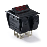
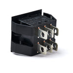
Rhodes 5 Pin Suitcase Amplifier Power Switch

Rhodes 5 Pin Suitcase Amplifier Power Switch
Replacement power switch for 5 Pin Rhodes Suitcase Amplifier
Share this Product
Product Details
Description
Wiring Diagram
FAQ
Description
Replacement Power Switch for Rhodes 5 Pin Suitcase Amplifier.Sold individually.
Wiring Diagram
• 5 Pin 100W Amp Power Switch Wiring DiagramFAQ
I bought a replacement power switch for a Rhodes. Looking at the original switch, it is a DPDT type while the new one I received is DPST. It looks like they are just using the posts to strap a cap across a couple transformer windings. Is this true?
The original switch has six lugs but is not a DPDT switch.
If you take a look at the Schematic for the Janus Power Supply (which can be found for free here. You will find that that the original switch is a DPST switch and that there are two lugs that are dedicated entirely for the Neon bulb and its current limiting resistor.
For 120VAC Mains wiring, the schematic shows:
You will find that the Neutral from the IEC terminates at one switch POLE
The LIVE coming from the fuse holder terminates at the other switch POLE
The THROW lug that mates with the NEUTRAL is connected to the BLK/RED, BLK/YELLOW & one lead of capacitor C5.
This lug is jumpered to the lug above it, which goes to one side of the neon bulb.
The THROW lug that mates with the LIVE is connected to the other side of C5 and the YELLOW wire.
The remaining lug for the neon bulb is connected to the BLK/BLK GREEN wires.
You will also see on the schematic that the BLK and the YELLOW wires are coming off the same exact tap on the transformer.
You will see that the wiring arrangement for 240VAC mains is different but is able to utilize the same switch and bulb. That is the main benefit to that original switch.
Those switches are no longer manufactured; which is unfortunate for Rhodes owners as well as vintage Marshall amplifier owners seeking a replacement.
That being said, the switch we offer is a very feasible replacement.
It is also a DPST switch. And as you noted it has 4 Lugs. The neon bulb and current limiting resistor are simply tied to the throw lugs. Therefore the wiring diagram included with the switch and found on the product page of the website under “WIRING DIAGRAM” should be sufficient instruction for a tech to replace the switch.
https://www.vintagevibe.com/products/rhodes-5-pin-100w-amplifier-power-switch
If you are not comfortable reading schematics, please remember that you are working with mains voltage and errors can result in serious damage to property or even death. Performing such service should be done with extreme caution and of course at your own risk.
 Our piano website


